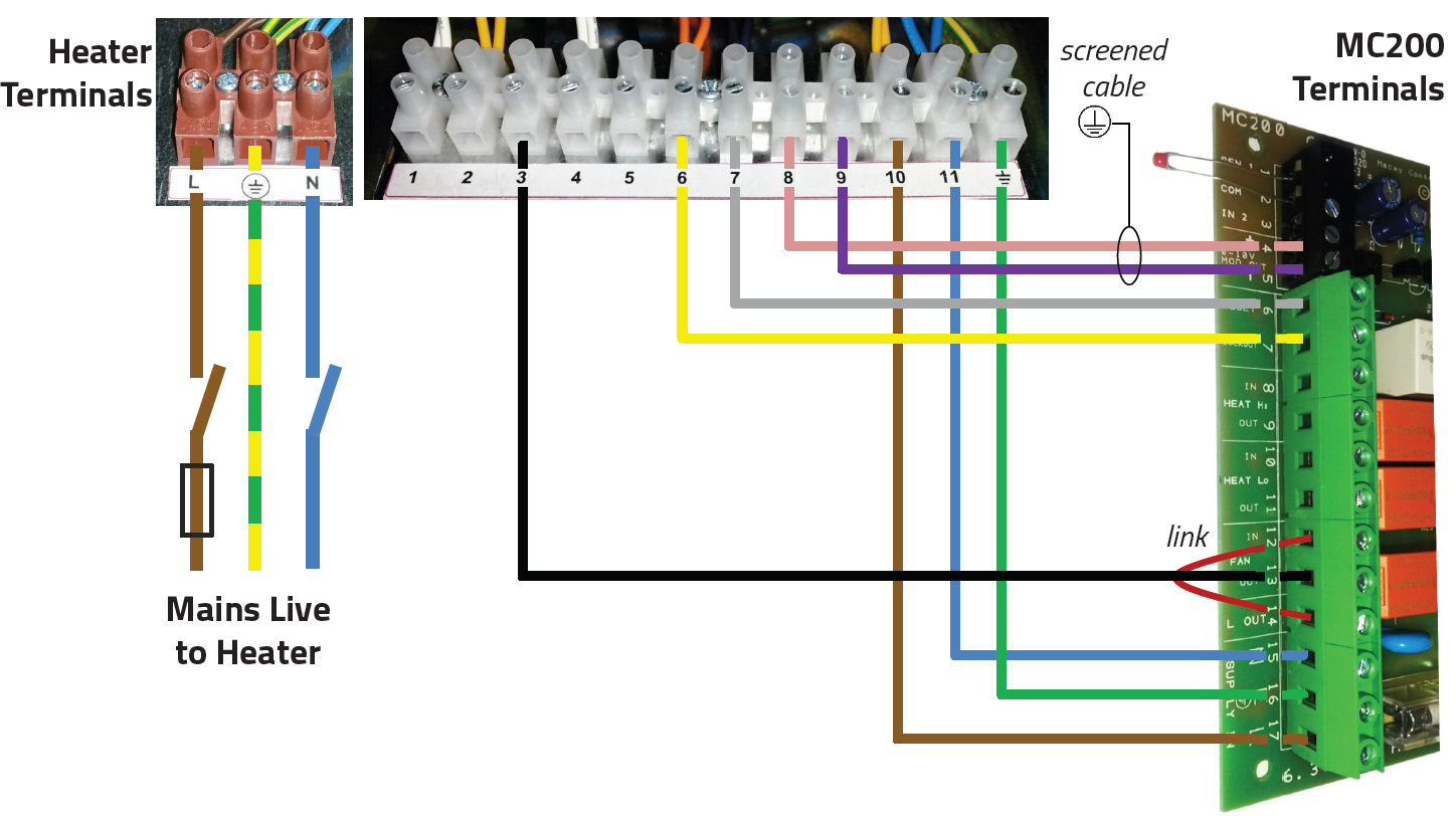
Interconnecting wiring between a MC200 and a Modulating LX Warm Air Unit
WARNINGS:
 WARNING: The next section must be carried out by a qualified person to current IEE regulations for Electrical Installations and any local regulations which apply.
 WARNING: The mains electrical supply to the MC200 should be taken from the appliance from heater terminals t10, t11 and t12 and through a local isolator fitted adjacent to the MC200.
 WARNING: We strongly recommend the use of a suitable screened cable for the 2-core 0-10vdc modulation input on terminals t8/t9.
 WARNING: Any sensor wiring MUST BE RUN SEPARATELY and apart from ALL other wiring. Under no circumstances must voltage be applied to the sensor connections.
 Note: Any sensor cable must be screened two core and a minimum of 0.6mm² if solid and 7 x 0.2mm² if multistrand. The screen must be grounded only at the MC200.
 Note: Burner Reset terminal is internally connected to NEUTRAL when the reset button is pressed.
Procedure
Wiring terminals for the MC200 are located beneath the electrical lower front cover. Wiring should be completed in conduit, for which knockouts are provided in the bottom of the casing.
Mains supply and control circuit wiring should be completed in cables not less than 0.5mm².
Interconnecting wiring diagram LX to MC200

